
Early Kick Detection System RFQ — Pit Volume, Return Flow, and Mud-Logging Fields
Buyers search kick detection, early kick detection, or early kick detection system when pit-gain and return-flow monitoring must sit inside a mud-logging RFQ — and the request often collapses to one vague line: "kick detection system." That hides the decisions that drive fit: which pit-volume sensors cover active pits and the trip tank, which paddle flow-out path reports relative outlet change, and how those signals feed the mud-logging unit for well-control warnings.
This page is not a rewrite of soft encyclopedia posts. Use advances in well control, well-control causes, indicators, and preventative actions of kick, why accurate pit-level monitoring is essential, the role of flow meters in preventing lost circulation and kick events, and drilling mud flow meters — flow dynamics for kick detection only as context. It is also not a rewrite of the related mud flow meter buyer guide pack (#20), which owns return-flow sensor RFQ alone. This page turns system-level early kick detection — pit volume plus return-flow comparison inside mud logging — into quote fields that feed live product pages and the mud logging solution brief, then request a quote.
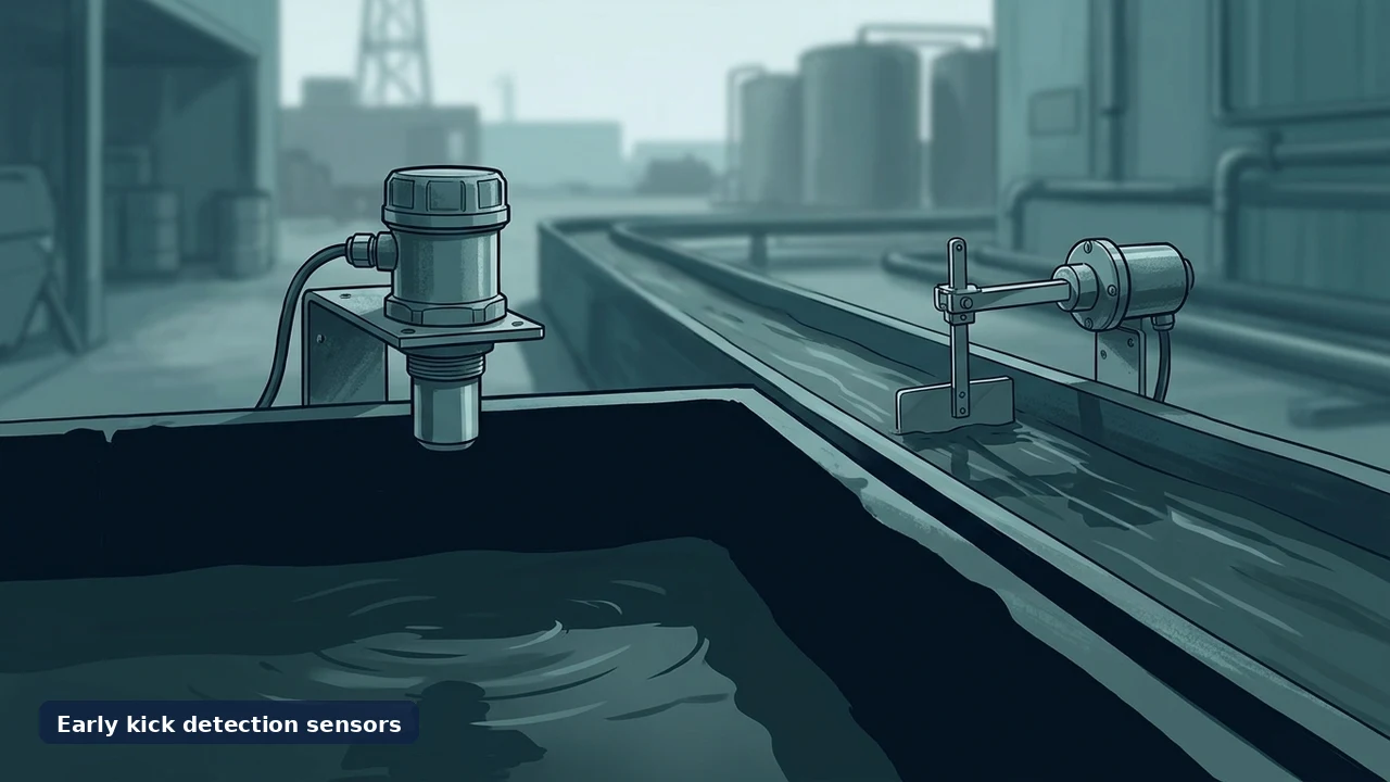
Start with duty, not with a system label
An early kick detection package in mud logging is a decision signal. Name what the signal must do before you ask for hardware:
| Duty | Question the RFQ must answer |
|---|---|
| Pit gain / loss | Continuous pit volume (and trip-tank) view so gain or loss trends are visible in time? |
| Return vs inlet | Will the unit compare outlet mud flow against inlet for leakage, formation fluid entry, kick, or blowout-forecast framing? |
| Trip tank | Dedicated trip-tank level monitoring during trips, or active pits only? |
| Alarms / interfaces | Which mud-logging acquisition unit, input type, and alarm / interface rules apply? |
| Hazardous area | EX type or intrinsically safe expectation; zone barriers in the Unit as published? |
The mud logging solution page frames the system around the data objective: units, sensors, monitoring, and supporting equipment — with measurements, rig interfaces, hazardous-area class, data workflow, and field environment defined up front. A typical unit includes gas detection (total gas + chromatograph), drilling sensors (depth, ROP, pump strokes, pit volume, mud temperature and density), DAQ, and a climate-controlled cabin. FAQ language on that page includes real-time kick and loss warnings for well control. Keep surface mud logging distinct from LWD/MWD.

Sensor path — map to published CNPS pages
Five live product pages cover the pit-volume and flow-out sensors that feed early kick / loss monitoring. Use only published figures; prefer body specs over sidebar Weight widgets if they conflict.
Pit volume — CNPS-ML11 — ultrasonic liquid level / drilling fluid volume. Power +15 V ~ 30 V DC (recommended +24 V DC); range 0.25 m to 5 m; output 4 ~ 20 mA; accuracy + 0.5% FS; working temp −40 °C ~ +60 °C; RH 5 ~ 95% RH. Install on a mounting rack with sound path clear and perpendicular to liquid; ≥25 cm from sensor end to highest liquid level; avoid fill lines, pipes, welds, ladders, and walls. EX type or intrinsically safe; zone barriers in the Unit.
Pit volume — wireless pit level — ultrasonic for active mud pits and trip tank; monitor pit-level changes for timely kick and mud-loss indication. Range 0.5–3 m; accuracy ±1 FS (as published); supply 3.5–5 VDC; output 0.5–2.5 V; security level IEC EEX iaII CT6 (as published); working temp −20 ~ 70 °C; IP67. Volume framing on page: Vs = cross-sectional area S × mud depth Ls.
Return flow — three paddle paths (relative outlet change only; no absolute calibration on published pages):
| Item | CNPS-FLM (paddle) | Wireless flow out | Wired paddle |
|---|---|---|---|
| Sensing | Proximity + curved test board; non-contact vs potentiometer wear | Paddle; relative outlet change; outlet vs inlet compare framing | Paddle; stainless; EX junction box; transmission separated from electrical |
| Baffle | 0–45° | 0–45° | 0 ~ 45° |
| Range | Weight on baffle; no absolute calibration | Weight mass change; no absolute calibration | 0–100% relative; no absolute range |
| Supply / output | 10–24 VDC / 4–20 mA | 3.5–5 VDC / 0.5 ~ 2.5 VDC | 24 VDC / 4 ~ 20 mA |
| Accuracy | — (not stated on PERFORMANCE list) | ≤1% F·S | ±2% FS |
| Temp / other | −20 — +80 °C; install outlet line / mud groove; free baffle swing; slope vs grit | −40 ~ 70 °C; IP67; EX or IS; zone barriers in Unit | −55 °C ~ +100 °C; 380 × 250 × 170 mm; EX or IS |
For paddle-path detail alone, see the related mud flow meter buyer guide pack (#20) and the three live flow-out PDPs — do not invent a live buyer-guide URL if unpublished.

Scope stack — install, signal, hazardous area, maintenance
- Install — pit / trip-tank mounting rack for ultrasonics; outlet line or mud groove for paddles; baffle free to swing; slope versus grit.
- Output type — 4–20 mA (ML11, FLM, wired paddle) versus 0.5–2.5 V (wireless pit / wireless flow); match the mud-logging unit input.
- Hazardous area — EX type or intrinsically safe as published; zone barriers in the Unit where stated; wireless pit security level as published. Ask for project documents — do not invent certificate numbers beyond page language.
- Mud-logging interface — acquisition system, scaling, pit-volume and inlet–outlet compare logic, cable or wireless receiver, kick / loss alarms.
- Maintenance — clear ultrasonic path; clean mud from paddle moving parts; adjustable baffle / weighting for relative range.
No invented system SKUs, absolute flow calibrations beyond published relative paddle language, prices, plants, case studies, or certificate seals beyond published product-page wording.
Early kick detection RFQ checklist

- Duty — pit gain/loss, return-vs-inlet compare, trip-tank coverage, or combined early kick / loss monitoring.
- Pit path — CNPS-ML11 and/or wireless pit level; active pits and trip tank count; pit cross-section if volume (Vs = S × Ls) is required.
- Flow-out path — CNPS-FLM, wireless paddle, or wired paddle; relative % change expectation (state clearly if absolute volumetric rate is required so review can flag it).
- Mounting — pit rack geometry and clearances (≥25 cm ML11 rule); outlet line / mud groove size; photos if possible.
- Signal and power — 4–20 mA or 0.5–2.5 V; supply as applicable (+15–30 V DC / +24 V recommended, 10–24 VDC, 3.5–5 VDC, or 24 VDC).
- Mud logging unit interface — acquisition system, input type, cable or wireless receiver; kick / loss alarm rules.
- Environment — ambient against published operating ranges; mud/solids load; cleaning plan for grit on paddles.
- Hazardous area — zone; EX / intrinsically safe expectation; documents required (cite published page language only).
- Related scope — gas detection, depth/ROP/pump strokes, mud temperature and density if the wider mud logging unit is in scope; keep LWD/MWD separate.
- Commercial — quantity, destination, need-by date; send via request a quote.
Send one brief
A useful early kick detection request fits on one page: duty, pit and flow-out paths, mounting, signal and power, logging-unit interface, environment, hazardous-area needs, related mud-logging scope, and commercial fields. Missing fields get flagged in review.
Ready to quote? Start from pit level sensor CNPS-ML11, wireless pit level sensor, CNPS-FLM Flow Out Sensor (Paddle Type), wireless flow out sensor, and flow out Sensor (Paddle) for mud logging unit, align scope with the mud logging solution page, then send the brief through request a quote.


